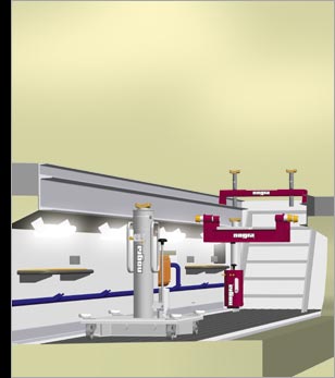
The central feature of a perfectly functioning workshop is the pit. Here, everything
must work hand in hand to keep the throughput times as short as possible. But
what is needed in an ergonomic pit? What must be taken into account? This raises
many questions, and we have explained some of the answers briefly below.
Length
Choose according to need, 21 m is ideal. A long vehicle should never block both
accesses.
Width 1050 mm outer edge of wheel rail for truck and bus workshops
(universal pits for all types of vehicles). If more than 1 pit is available,
the widths may be of variable size in order to have an optimum width for each
vehicle.
Depth 1390 mm for trucks and vehicles with ample ground clearance. 1490
mm for buses and vehicles with low ground clearance. Note: depth of pit and
free space of the vehicle should allow a comfortable standing height (pit depth
for nogra pit jacks see page 9). With a depth of more than 1600 mm, the regulations
for forced ventilation are to be observed.
Shape of pit We recommend an enlarged width of the pit below the edge
on both sides by approx. 200-270 mm. Thus, the working space will be enlarged
and space is gained for maintenance conduits, illumination and shelves.
Stowage space Additional stowage space can be planned for oil drums,
stationary greasing equipment etc. You may also plan space for mobile pit jacks.
Parallel 0/+5 mm
Regulations Please observe existing local regulations available from
your authorities.
Barriers/pit cover Pits must be secured in order to prevent accidents.
This may be achieved by setting up chains to block access approx. 500 mm from
the edge of pit. With longer service intervals, it may be advisable to completely
cover the pit.
Access There should always be 2 stairs. Emergency exits are not allowed
if they replace the stairs.
Oil trap Use according to local rules.
Supply line PVC ø 300 for electrical cables, compressed air, oil
hoses etc.
Access Always 2 stairs.
Light switch Beside the access stairway, can be installed in the cable
conduit for pit lights.
Lighting Pit lights in staggered arrangement. They must not project into
the pit.
Tool tray These are much cheaper than recesses in the concrete.
Power socket 220 V/16 A flush mounted in the conduit.
Compressed air A service unit in the pit is recommended.
Pit depth Ideal for trucks only, pit 1390 mm (1490 mm for buses).
Cable conduit For electrical installation (PVC), flush mounted. Light
switches and power sockets.
Wheel rails approx. 80-100 mm above the ground.
Pit width approx. 900-1050 mm. Wider pits are no longer suitable for
all vehicles (twin wheels).
Pit length Ideally approx. 21 m (the longer the better).
Oil trap according to local regulations.
Barrier Installed approx. 500 mm outside the pit.
Stowage space Dimensions, e.g.
w x l = 600 x 2200 mm (for oil barrels, lubricating equipment etc. Appropriate
in pits used for oil changes and lubrication only).
Pit design Floor and walls lined with panels, pit edging galvanised.
Extraction Observe regulations
Choice of proper pit edging The information on this
page should help you to choose the right edging. The following criteria should
be observed.
Safety How is the passage to and from the pit? You may omit the wheel
rails if it is possible to enter and leave the pit in a straight line. In
this case, the pit may be built wider. Never omit the wheel rails if this
is not the case or if the pit can only be left in reverse gear. Marking of
passage routes is recommended as a guide.
Loading capacity In many cases, the edge of the pit acts as a rail
for the trolley of the pit jack. In order to comply with static requirements,
the profiles should not be too small. See this page for dimensions. Anchoring
irons should be welded to the backs of the profiles at regular intervals (200-300
mm spacing according to static requirements). The profile projects by 5-10
mm over its entire length. If using pit jacks with a non-adjustable trolley,
receivers should be installed, the dimensions of which are to be given by
static calculations.
Pit cover Conventional covers consist of gratings
or wooden planks. Covers are always useful if the pit is only temporarily
in use. If wheel rails are used, the cover should be such that vehicles can
pass over it. If the pit is used frequently, barriers made of upright bars
or chains may be sufficient.
GE I Standard pit for trucks and buses. Pit jacks up to 20 t. Economical
pit edges without notable disadvantages. Pit jack and supporting bridge can
be easily combined.
GE II Wide, safe pit for pit jacks up to 20 t. There is a working space
of ca. 1000 mm available. Receivers should be installed for pit jacks from
20 t.
GE III Standard pit for heavy vehicles. 2 different traverse levels
for the pit jack and the supporting bridge are advantageous. The working space
(overall width) is considerably greater than for GE I at approx. 950 mm. If
FI 70 x 70 is used, this is especially suitable for vehicle-bearing pit covers.
Receivers should be installed for pit jacks from 20 t.
Working
space (overall width) The maximum working space is obtained if profiles
are used which are closed at the top (U-profiles or I-girders). This is increased
if circumstances allow the omission of wheel rails and pit cover edgings. The
wheel rails reduce the remaining working space particularly for vehicles with
low ground clearance. A recess beneath the pit edging creates stowage space
and improves the access beneath the pit jack trolley.


